Building an IoT Webcam
This is a re-upload of a project I worked on during Winter quarter 2017 with Nathaniel Wong and Ben Lim in the initial offering of EECS 326 Electronic Systems Design.
Introduction
Our team’s task was to design a lightweight, low power, web-based camera using low level componets. Specially, our design uses a SAM4S8B Atmel microcontroller, an OV2640 camera module, and a Zentri AMW004 wireless module. The end product is fully encased in a 3D printed enclosure provides physical access for resetting the microcontroller and wireless module. It also provides holes for the power supply, camera lens, and wifi antenna. Finally, when a user access the device wia the web, the camera captures a JPEG file that is sent to the microcontroller (MCU) via a TWI (I2C), and then uploaded to the WiFi module to be accessed via websockets. This process updates the images to stream a series of real time images to the website, allowing the user to view the webcam from anywhere in real time.
Design Process
PCB Design
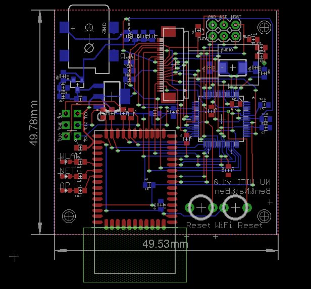
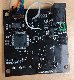
After prototyping our design on separate break-out boards for each of the 3 main components (MCU, camera, and WiFi), we moved to integrate all the components onto a single PCB less than 50mm x 50mm.
Layout Approach
Each of the breakout boards included additional hardware for develpment and debugging purposes which were removed for the final design (such as the FTDI chip and microUSB port.) The size of the board was set at 50mm x 50mm in Eagle.
The MCU was laid out first because of the number of connections required. Next, the camera and WiFi chips were placed. Finally, the power supply components were added. Routing the components with the most interfaces and careful planning allowed the routing process to proceed without too much difficulty. To interface with the enclosure, 3 standoff holes were inserted into the corners of the PCB.
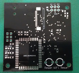
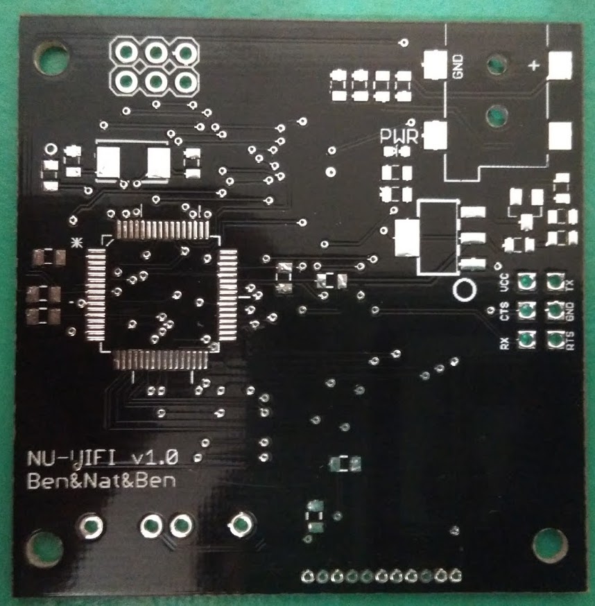
After designing our board and ensuring that it passed the design rules check, we processed our design using the CAM file provided by the manufactuer and sent the PCB to be built.
C Code
Our software architecture separated the functions of the MCU, camera, and WiFi into separate C files. The major compoenents of the embedded system are in: init.c, main.c, camera.c, and wifi.c.
The init.c file is responsible for all pin initializations on the MCU. The main.c file contains all necessary calls to other functions and the main loop of the code. Wifi.c and camera.c along with their respective header (.h files) are responsible for the implementation of all functionality required for proper communication between the microcontroller and the wifi and camera chips respectively. These are the primary C source files that were written for the implementation of the embedded system; however, there are another two classes of source files that were instrumental in the design of the C Code. These come in the form of library code (for the OV2640 camera and an interface for a timer) and the example code provided in Atmel Studio.
Pin Initializations
Pin initialization is an critical part of the C code for the webcam system. The pin definitions are the interface between the higher level implementation in other files and the specific changes in hardware state that must occur to support these changes. These initializations occur in two primary places: conf_board.h and init.c. The conf_board file consists exclusively of #define statements linking the feature requested to the hardware supporting it. All connections between pins were recorded (Figure 3) during the breakout board phase of the project.
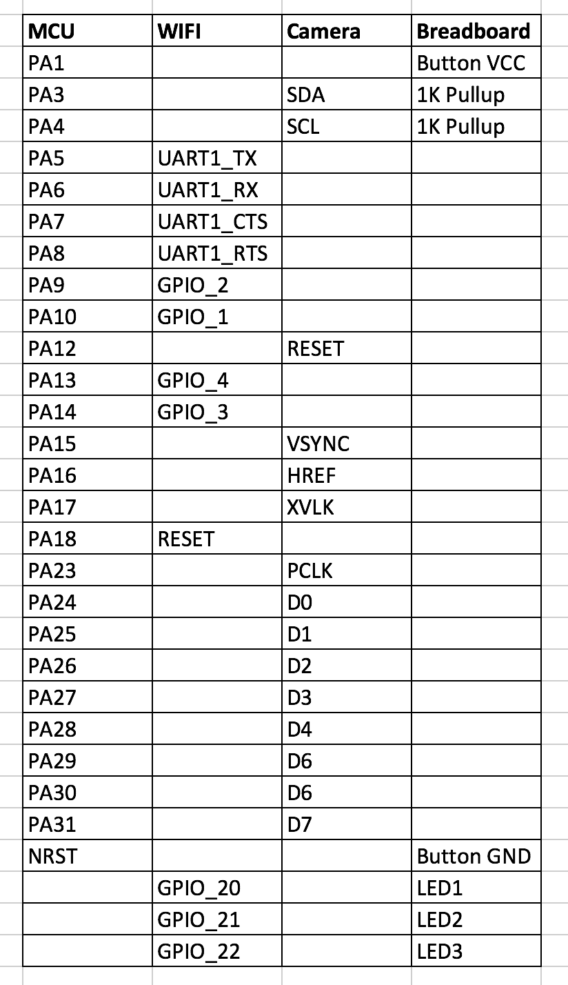
The only pin definitions implemented in the C code are the connections between the MCU and another device. An example of the #define code for the camera data pins is shown below.
1
2
3
4
5
6
7
8
9
#define CAM_D0				 PIO_PA24_IDX
#define CAM_D1				 PIO_PA25_IDX
#define CAM_D2				 PIO_PA26_IDX
#define CAM_D3				 PIO_PA27_IDX
#define CAM_D4				 PIO_PA28_IDX
#define CAM_D5				 PIO_PA29_IDX
#define CAM_D6				 PIO_PA30_IDX
#define CAM_D7				 PIO_PA31_IDX
#define CAM_DATA_BUS_FLAGS              (PIO_INPUT | PIO_PULLUP)
The init.c file is largely responsible for calling built-in initialization functions that use the pin definitions from conf_board.h as input parameters. Some example code for the camera data lines is shown below.
1
2
3
4
5
6
7
8
9
10
11
12
13
14
15
16
// PA24: CAMERA D0
gpio_configure_pin(CAM_D0, CAM_DATA_BUS_FLAGS);
// PA25: CAMERA D1
gpio_configure_pin(CAM_D1, CAM_DATA_BUS_FLAGS);
// PA26: CAMERA D2
gpio_configure_pin(CAM_D2, CAM_DATA_BUS_FLAGS);
// PA27: CAMERA D3
gpio_configure_pin(CAM_D3, CAM_DATA_BUS_FLAGS);
// PA28: CAMERA D4
gpio_configure_pin(CAM_D4, CAM_DATA_BUS_FLAGS);
// PA29: CAMERA D5
gpio_configure_pin(CAM_D5, CAM_DATA_BUS_FLAGS);
// PA30: CAMERA D6
gpio_configure_pin(CAM_D6, CAM_DATA_BUS_FLAGS);
// PA31: CAMERA D7
gpio_configure_pin(CAM_D7, CAM_DATA_BUS_FLAGS);
The camera
The camera.c file was responsible for the implementation of the functions required to communicate and store information from the OV2640 camera module. There are several initialization and configuration functions as well as functions to record data from the camera and do some initial processing. Much of the input/output code for the setup of the two wire interface (I2C) and the vsync interrupts required minimal changes from the example project provided by Atmel Studio.
However, the start_capture() and find_image_length() functions required more thought. The start_capture() function captures an image from the camera upon a rising edge of the vsync and calls the find_image_length function to confirm that it received a valid JPEG image and if appropriate find the length of the image. On the MCU the image is saved in a buffer. One of the challenges we encountered was how this buffer should be implemented. Ultimately, the buffer was simply declared in camera.h as:
1
2
#define buf_size 100000
uint8_t g_p_uc_cap_dest_buf[buf_size];
However, due to having another (overly large) buffer for the responses from the wifi chip, we encountered memory issues at compile time stating that there would not be sufficient memory on the stack for the buffer. We decided to try dynamically allocating memory on the heap for the buffer using malloc and free. Using this method we were able to receive data from the camera; however, it significantly over-complicated the problem. Reduction of the size of the wifi response buffer solved this issue and allowed us to go back to a far simpler buffer.
The next task was to determine if there was a valid JPEG image present in the MCU’s memory. A valid image has a start of image flag (0xFFD8) followed by the image data and finally by the end of image flag (0xFFD9.) The approach for this function was to start at the address of the byte in the buffer and search for 0xFF followed by 0xD8. Once this two byte pattern was found, the address of the 0xFF byte was saved. The linear search then continued until finding 0xFFD9, at which point the address of 0xD9 was saved. This constitutes a valid image and its length was determined as the final address subtracted from the initial address.
Since the length and position of the JPEG image within the buffer are unknown, more efficient search methods were initially considered, but they were not thoroughly pursued. The same result would also be attainable using only array indices. However, for debugging purposes it was advantageous to have the exact memory addresses in order to examine the contents of memory and confirm the results of the function. To suit this debugging process, the find_image_length() function was implemented using pointers.
1
2
3
4
5
6
7
8
9
10
11
12
13
14
15
16
17
18
19
20
21
22
23
24
25
26
27
28
29
30
31
32
33
34
35
36
37
38
39
40
uint8_t find_image_len(void)
{
    uint8_t found_len = 0;
    uint8_t* mem_pos = &g_p_uc_cap_dest_buf;
	uint32_t count = buf_size;
	uint8_t SOI = false;
	while (count > 0) {
		if (*mem_pos == 0xFF) {
			mem_pos += 1;
			if (*mem_pos == 0xD8) {
				SOI = true;
				g_p_uc_cap_dest_start = mem_pos -1; //find the starting location
				break; // error: SOI not found yet
			}
		}
		mem_pos++;
		count--;
    }
    if(SOI == false) return 0;
    while (!found_len)
    {
      // Check the next byte for ff flag
      if (*mem_pos == 0xFF)
      {
        mem_pos += 1;
        if (*mem_pos == 0xD9)
 	 {
          Found_len = 1;
          jpeg_image_length = mem_pos - g_p_uc_cap_dest_start;
          return 1; // Success: EOI found
        }
        else if (*mem_pos == 0xD8)
{
          return 0; // error: SOI found before EOI
        }
        else mem_pos += 1;
      }
      mem_pos++; //not a flag, check next;
  }
}
Wifi
Wifi.c (and its .h file) are responsible for the communication (over USART) between the Zentri AMW004 wifi chip and the MCU. As in the camera.c and camera.h files, there are several configuration functions and interrupt handlers that require relatively few changes from the example code available across several of the example projects.
The most important feature of the wifi.c file is the ability for the MCU to give commands to the wifi chip over USART. Using the ZentriOS command API, the wifi chip can be given commands in the form of text communication over the USART line between the MCU and the wifi chip.
The function primarily responsible for this is write_wifi_command(char* comm, uint8_t cnt). This function takes a command to issue to the wifi chip as a pointer to an array of characters and an 8-bit value called cnt that defines the maximum amount of time the MCU can wait for an acknowledgment of the command from the wifi chip. Aftering determining if the wifi chip is ready to receive another command, the MCU invokes the built-in usart_write_line function to send the command. The usart line to send the data through was defined in the wifi.h file.
1
2
3
4
5
6
7
8
9
10
11
12
13
14
15
16
17
18
19
20
21
22
void write_wifi_command(char* comm, uint8_t cnt)
{
	usart_write_line(BOARD_USART,comm);
	last_cmd = comm;
	counts = 0;

	while(counts < cnt)
{
		if (g_ul_wifi_response_flag)
		{
			g_ul_wifi_response_flag = false;

			if(strstr(latest_wifi_response, unknown_cmd) ||      strstr(latest_wifi_response, invalid_arg))
			{
				 usart_write_line(BOARD_USART,*comm);
			}
			else break;
		}
		counts++;
		delay_ms(1000);
	 }
}
Another critical function in the wifi.c file is write_image_to_file(). This function needs to use the command API to write the entire JPEG image captured from the camera to the wifi chip. This function first checks that the image is a valid JPEG, and then proceeds to delete the old image and create a new file of the new image’s length. To pass the image length into the command string, sprintf was used. Then, the image can be written from the MCU to the wifi chip one byte at a time by using the starting address and ending address of the image that were saved in the find_image_length function.
1
2
3
4
5
6
7
8
9
10
11
12
13
14
15
16
17
18
19
20
void write_image_to_file(void)
{
	if(!jpeg_image_length)
{
		return;
	}
	char* delete_cmd = "file_delete webcam/images/img.jpg\r\n";
	uint8_t cmd_length = 39;
	char new_cmd[cmd_length];// = "file_create img.jpg  \r\n";

	sprintf(new_cmd,"file_create webcam/images/img.jpg %d\r\n", jpeg_image_length);
	write_wifi_command(delete_cmd, TIMEOUT);
	write_wifi_command(new_cmd, TIMEOUT);


	for(uint8_t* i=g_p_uc_cap_dest_start; i < g_p_uc_cap_dest_start+jpeg_image_length; i++)
	{
		usart_putchar(BOARD_USART, *i);
	}
}
Processing the wifi chip’s response is another important task that was implemented in the wifi.c file. When the wifi chip completes a command, there is a rising edge on PA10 (GPIO_1 of the Wifi), it sends a response over USART. Each byte that arrives gets stored in the input_line_wifi buffer. When the command is complete, an interrupt for the MCU is generated, and it calls the process_data_wifi function. Process_data_wifi checks the contents of the buffer against a number of potential responses (including “Set OK”, “Unknown command”, “Success”, “Invalid argument”, “File created”, etc) and sets the appropriate flags and variables to indicate this result.
Main
The main file calls the all the initialization and setup functions needed for the system clock, the board’s pins, the USART communication with the wifi chip and the camera. It then waits for the wifi chip to connect to the network and disables the command prompt as well as the command echo. At this point flow control can be enabled to ensure that the wifi chip does not miss any information from the MCU. The program then enters its main loop. In the loop, it checks if the soft access-point button has been pressed to reassociate the wifi chip with a new network and checks that the chip is connected and has an open websocket. If there is a connection and an open socket, it then captures an image and sends an update to the stream to force the load of a new image. If this condition did not pass, there is no image taken and the MCU waits one second and tries again.
Challenges
The majority of our challenges stemmed from subtle changes from the example projects to our system. For example, using PLL-B instead of PLL-A for the TWI communication between the MCU and the camera was a easy change to implement; however, discovering that this was the issue took a great deal of time. Throughout the process (from breakout boards, to trying our PCB, to using the provided PCB design) we experienced repeated issues with inconsistencies in the run-time behavior as a result of solder connections. These issues were obvious when the issue was a completely new bug or infinite loop, but it was much more difficult to determine the source of the issue when it was an area that was also being tested in software.
The timeline of the course (finalizing the PCB design before completing all software) resulted in a number of difficult to diagnose bugs. The most significant of which was the incorrect wiring of the D7 data line from the camera to the MCU and the RESET line of the camera. These changes were noted so that we could attempt to correct these errors when the PCB arrived by cutting the appropriate traces and soldering wires correct the mistake. With these new connections made we tried stepping through the code that ran on the breakout board. The code would run through the majority of the initialization code until it got to configure_camera(). At this point, the code got stuck in an infinite loop at while (ov_init(BOARD_TWI) == 1). Stepping into this function call, we observed that the TWI communication would always return not acknowledge (Nack) and the function would be called again trying to establish communication.
We attempted to jump the connections however it did not resolve the issue, meaning that the jumps were not able to make a good connection. However, this specific issue would be solved with a PCB revision.
3D Enclosure
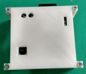
We started with a simple outline of the box with some allowances for the fit (this turned out to be very useful for our jumper wires. We first just printed the standoffs to ensure that they were of the right dimensions to fit the board. We also soldered large components to a test board such as the DC jack and the buttons as physical test points for our 3D print.
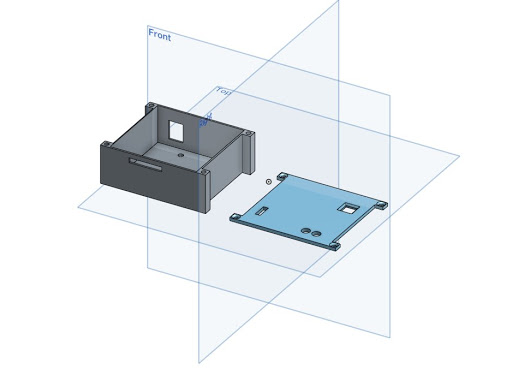
We iterated through the design twice to ensure that the dimensions were right before we were able to obtain a container that fit our box perfectly. We found that a dimension of 2.6mm was the best fit for the screws that we were given for our self-threading design.
Within the 10 week timeframe of this course, we would not have time to make a PCB revision to address the hardware bugs we discovered from our original design. So, we moved to adapt our code to the provided demo PCB design. The new board worked with minimal changes to our code, confirming that our issue was in fact due to hardware.
With the demo board, we were able to take images and transfer them in near real time to the Zentri Wifi chip and server.